 |
|
|
Using Frameworks, model the structure shown in Figure
2.1 . All
members are made of carbon steel, and use the W130x24
cross-section. Report
the deflections at node A, the reactions and node D, and the
member forces in member A - C.
The circles in the members in the middle of the structure
indicate moment releases.
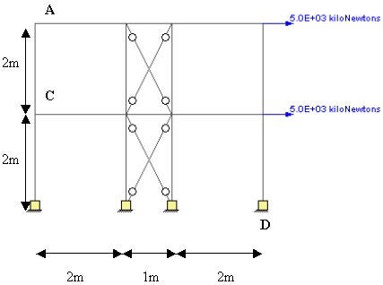
Figure 2.1 - Sample Frame to be modeled
Back
to Top 

The first thing that is seen on starting the programs is the dialog box in Figure
2.2 . This allows you to pick the units that you will be using for your structure, as well as the initial screen dimensions and the grid spacing. The grid spacing is also the snap resolution used in the program. Both the screen dimensions and the grid spacing can be changed later at any time using the
Zoom and Set Grid Spacing functions. Once the units have been set, the only way to change them for the same structure is by editing the
StructureXML text.
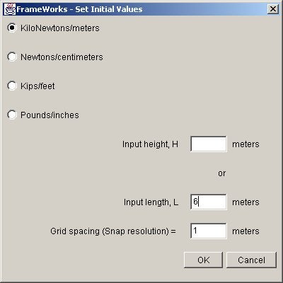
Figure 2.2 Dialog box to set units and
initial dimensions
Pick the “KiloNewtons/meters” option,
and input a Length of 6 meters, and grid spacing (snap
resolution) of 1 meters.
Back
to Top
-
Add Members - Go to
the “Function” menu, and select “Add
Member”. Click
once to add the first node of the member, move the mouse,
and click again for the second node.
Repeat the process until you have a structure like
that shown in Figure
2.3. Alternatively, you can copy and paste the
text from demoStep1.xml
into the text area from selecting "File"
à
"New StructureXML"
to get to this step.
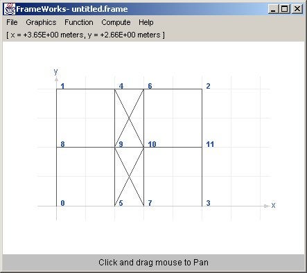
Figure 2.3 - Members added
-
Release
Internal Member Moments - Release the internal
moments in the members in the middle of the structure as
shown in Figure
2.1 . Select
“Member Moment Release” from the “Function”
menu, and click on the members to release moments.
Release the moments at the appropriate nodes, and click on
the “Release” button.
When done, the structure will look like that shown in
Figure
2.4. Alternatively, you can copy and paste the
text from demoStep2.xml
into the text area from selecting "File"
à
"New StructureXML"
to get to this step.
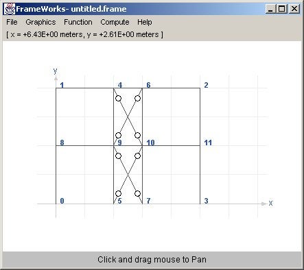
Figure 2.4 - Structure after member moments
have been released
-
Enter
Member Properties - Once all the members have been
added, enter their member properties.
In this example, all members are W130x24 and made of
carbon steel. From
the “Function” menu, select “Enter Member
Properties”. This
will bring up the window shown in Figure
2.5 . From
the drop down menus on the right hand side, select the “W”
section, and then select “W130x24”.
Next, select “CarbonSteel” from the drop
down menu on the bottom right.
Select the “Apply to all members” option
(default option), and click on the “Apply” button.
Alternatively, you can copy and paste the text from demoStep3.xml
into the text area from selecting "File"
à
"New StructureXML"
to get to this step.
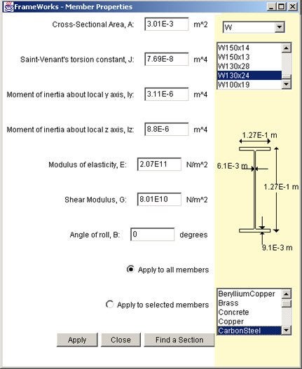
Figure 2.5 - Member Properties Panel
-
Constrain
Node - To constrain a node, select “Constrain
Node” from the “Function” menu.
This will bring up another window as shown in Figure
2.6 . Next,
click on the nodes to be constrained on the main screen.
Selected nodes will be highlighted in blue.
Then check the directions the nodes to be
constrained, (in this example, check all displacements and
rotations), and click on the “Constrain” button.
The constrained nodes should be drawn in yellow, as
shown in Figure
2.7. Alternatively, you can copy and paste the
text from demoStep4.xml
into the text area from selecting "File"
à
"New StructureXML"
to get to this step.
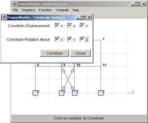
Figure 2.6 - Constrain Nodes Panel
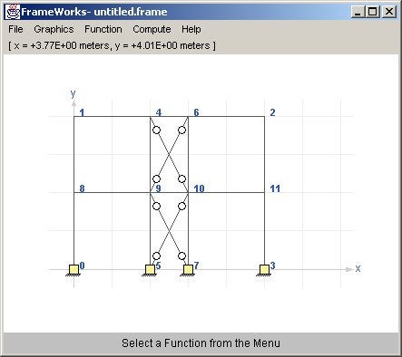
Figure 2.7 - Nodes Constrained
-
Load Nodes
- To apply a load on a node, go to the “Function”
menu, and select “Load Node”.
This will bring up the window shown in Figure
2.8 . Next,
go back to the main window and click on the nodes to be
loaded. Selected
nodes appear highlighted in blue.
Then input the loads to be applied (in our case 5000
kN in the positive x direction), and click on the “Load”
button. The
nodal loads should appear on the main screen as shown in Figure
2.9. Alternatively, you can copy and paste the
text from demoStep5.xml
into the text area from selecting "File"
à
"New StructureXML"
to get to this step.
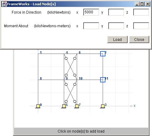
Figure 2.8 - Load Nodes Panel
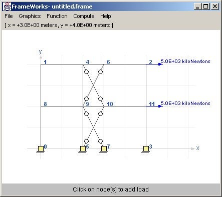
Figure 2.9 - Nodes Loaded
Back
to Top
-
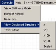
View
Displaced Structure - To view the displayed
structure due to the applied loads, select “View
Displayed Structure” from the “Compute”
menu. Different
magnification factors may be chosen to properly view the
displayed structure. In
this case, select “View Displayed Structure à
x1”. This
will show the displacements magnified by a factor of 1 shown
below in Figure
2.10 .
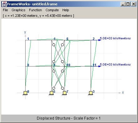
Figure 2.10 - Displaced Structure
-
View
Member Forces - To view the forces developed in the
members as a result of the loads applied, select “Member
Forces” from the “Compute”
menu. Click on
a member to view its forces, and a new dialog-box will pop
up showing the member forces (Figure
2.11). In
our case, click on member 1-8 (or member A-C as shown in Figure
2.1). The
sign convention used is the right hand rule, the positive x
direction runs from the start node to the end node.
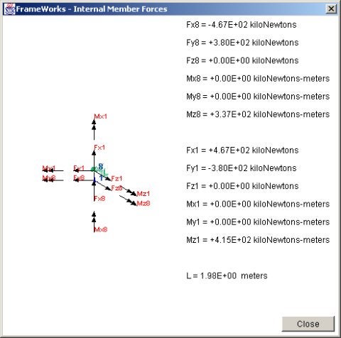
Figure 2.11 - Member Forces Panel
-
View Reactions
- To view the reactions at the constrained nodes due to
the applied loads, select “Reactions”
from the “Compute”
menu. This will
compute the reactions and display them on the main screen.
If the numbers look crowded, use the “Zoom
à
Window” option from the “Graphics”
menu, and zoom in on the node. This will change the
main screen to display the structure as shown in Figure
2.12 .
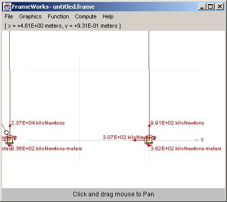
Figure 2.12 - View Reactions
-
Text Output
- To view the results of the computations in a text
format, select “Text
Output” from the “Compute”
menu. This will
bring up a window with the text output of the computations
as shown in Figure
2.13. If
running the programs as an application, select “Save
As…” from the “File” menu in the text
window, which will allow the user to save the text output on
the local hard-drive. If
running the programs as an applet, highlight and copy
all the text from the text area, and paste it in any text
editor. This
will allow the results to be saved on the local machine.
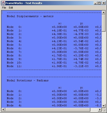
Figure 2.13 - Text Output of results
Back
to Top
- If running the program as an application, select “Save” from the
“File” menu to save the structure in binary format on the local hard drive. The saved structure can be retrieved later by selecting
“Open” from the “File” menu.
To save the structure in the StructureXML text format, select
“View StructureXML” from the
“File” menu. This will bring up the StructureXML text window. Next select “Save” from the “File” menu to save the XML text on the local hard drive.
- Running the program both as an applet and as an application let’s you save your structure to the server over the Internet. Select
“Save to Server” from the
“File” menu. This will upload the structure in binary format to the server running the applet. The file can later be retrieved by selecting
“Download from
Server”.
To save the structure in the StructureXML format when running as an applet, select
“View StructureXML” from the
“File” menu. This will bring up the StructureXML text window. Next, select “Select All”, followed by “Copy” from the “Edit” menu and paste the copied text to any text editor and save it on the local hard drive. To retrieve a structure from the XML later, open the XML text using any text editor, copy the StructureXML, and paste it on the text window from the
“New StructureXML” option in the
“File” menu and hit the “OK” button.
Back
to Top
|
|
|
|
|
|
|
The functionalities available in Frameworks can be broken into four main groups, which are
simply the menu items that are present in the program.
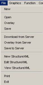
Figure 3.1 - File Menu Functions
-
New - Creates a new structure and clears the old
structure from memory.
-
Open - Opens a structure saved in binary format
from the users hard drive.
Not available when
running as an applet.
-
Overlay - Overlays another structure saved in binary format from the users hard drive onto the existing structure. The program increments the node numbers of the second structure with the number of nodes present in the first structure.
Not available when running as an
applet.
This would allow, for example, different users to work on different parts of a structure. Once the parts have been created and saved, they can all be overlaid to form the whole structure.
-
Save - Saves structure in binary format on
users hard drive. Not
available when running as an applet.
-
Download from Server - Downloads structure
saved in binary format in a server over the Internet using
TCP. Applets
can only download structures from a server that has the same
host name as the web server from which it originated.
-
Overlay from Server - Overlays another
structure saved in binary format by downloading the second
structure from a server over the Internet using TCP.
Applets can only overlay structures from a server
that has the same host name as the web server from which it
originated.
-
Save to Server - Saves structure in binary
format to a server over the Internet using TCP.
Applets can only save structures to a server that
has the same host name as the web server from which it
originated.
-
New StructureXML - Starts a new StructureXML
document (see Section 4).
If running the programs as an application, then File à
Open opens a dialog box that lets the user open a text (XML)
document from their hard drive.
Users running the program as an applet can copy a
StructureXML text from a local file, and paste it on the
textarea.
-
Edit StructureXML - Lets
the user edit their structure as a text (XML) file.
-
View StructureXML - Lets the user view their
structure in the StructureXML format.
If running as an application, File à
Save lets the user save the structureXML document in their
hard drive. Applet
users who want to save the StructureXML text must highlight
all the text in the textarea, copy it, and then paste it on
a text editor to save it on their hard drive.
-
Exit - Closes the program and clears the
structure from memory.
Back
to Top
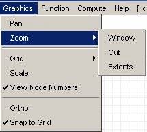
Figure
3.2 - Graphics Menu Functions
-
Pan - Allows the user to “pan” or move a
structure around the screen by clicking and dragging the
mouse.
-
Zoom -
-
Window – Zooms in on a structure, in the rectangle created by clicking and dragging the mouse on the screen.
-
Out – Zooms out by a factor of 0.5x.
-
Extents – Zooms to fill the full screen with the structure.
-
Grid -
-
On – Lets the user turn on, or turn off the
grid lines.
-
Set Grid Spacing – Allows user to explicitly
set the grid spacing.
This is also the “snap to grid” resolution
used by the program.
-
Scale - Toggles the scale visibility to on or
off.
-
View Node Numbers - Toggles node numbering to
on or off. The node numbering can be turned off, if
for example, the structure gets large and the node numbers
start cluttering the screen.
-
Ortho - Toggles ortho mode to on or off.
When in ortho (orthogonal) mode, the user will only
be able to draw horizontal and vertical members.
-
Snap to Grid - Toggles snap to grid mode to on
or off. When in
snap to grid mode, the start and end of members created by
clicking the mouse will snap to the grid lines.
Back
to Top
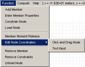
Figure
3.3 - Function Menu Functions
-
Add Member - Adds a member by clicking the
mouse twice. The
first click records the first node coordinates, and the
second click records the second node coordinates
-
Enter Member Properties - Brings up the Edit Member Properties
window (Figure 3.4), which allows the user to enter the member properties for
the structure. The user can set values for the member properties for all the members at once by selecting “Apply to all members”, and after setting the member properties, clicking on the “Apply” Button. To set values member property values for individual members, first select “Apply to selected
members” after setting the values. Next go back to the main screen and click on the members you want to select. Selected members appear blue.
Figure
3.4 - Enter Member Properties Window
In
addition to the member cross-sectional area and modulus of
elasticity, this window lets the user set values for the
Saint-Venant’s torsion constant, moment of inertia about the
local y and z axis, the shear modulus, and the angle of roll.
Here the angle of roll is defined as “the angle,
measured clockwise positive when looking in the negative x
direction, through which the local xyz coordinate system must
be rotated around its x axis, so that the xy plane becomes
vertical with the y axis pointing upward (i.e., in the
positive direction of the global Y axis).
For the special case of vertical members (i.e., members
with centroidal or local x axis parallel to the global Y
axis), this angle is defined as the angle, measured clockwise
positive when looking in the negative x direction, through
which the local xyz coordinate system must be rotated around
its x axis, so that the local z axis becomes parallel to, and
points in the positive direction of the global Z axis.”
The positive x axis, is the axis defined by the
start node (the node generated by the first click in the “Add
Member” mode) and end node (the node generated by the
second click in the “Add Member” mode) of the
member.
Clicking on the “Find a Section” button brings
up the window shown in Figure
3.5. This
window allows the user to compare two cross-sections, and also
has the functionality to match the section on the right with
the section on the left based on the largest section modulus.
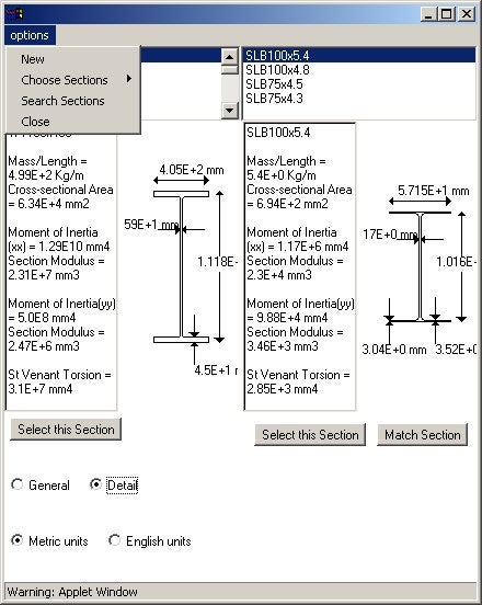
Figure
3.5 - Find Section Window
The sections database can also be queried by
selecting "Search Sections" in the "options"
menu. This will bring up the subpanel shown in Figure
3.6. Here the user can input any known parameters, and
all possible matches will be shown on the panel.
Finally, clicking on the "Select this Section"
button will select the section and go back to the "Enter
Member Properties" window.
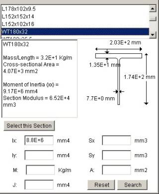
Figure
3.6 - Search Section Subpanel
-
Constrain Node - Allows the user to constrain
nodes. Frameworks
brings up the window shown in Figure
3.7 , and lets the user constrain nodal displacements
and nodal rotations in the x, y, and z directions.
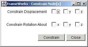
Figure 3.7 - Constrain Node Window
-
Load Node - Allows the user to load nodes. Nodes are selected by going back to the main screen and clicking on the nodes to
select them. Selected nodes have a blue box drawn around
them. The window shown in Figure 3.8 appears which lets the user apply nodal forces
and moments in the x, y, and z directions. These
forces are in the global coordinates.
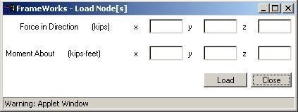
Figure 3.8 - Load Node Window
-
Member Moment Release - Allows the user to
release moments on a member.
Releasing a moment creates a hinge at the end of the
member, making it incapable of transferring moment forces,
much like a truss member.
This lets you create a frame structure, with truss
elements. Select
this option, and then click on a member to release moments.
Released moments show up as a circle on the main window.
-
Edit Node Coordinates - Allows the user to change node coordinates. This can be done in two
ways:
- Click and Drag Node – This option lets the user change a node coordinate by clicking on a node to select it, and then clicking again to set the new coordinates.
- Text Input – This option lets the user change the node coordinates by typing the new coordinates. First select this option, and then click on any
node.
-
Remove Member - Allows the user to remove
members from the structure.
Select this option, and then click on a member to
remove.
-
Remove Constraints - Allows the user to remove
any nodal coordinates.
Select this option, and click on a node to remove its
constraints.
-
Unload Node - Allows the user to unload a
node. Select
this option, and click on a node to unload.
Back
to Top
-
View Stiffness Matrix - This option brings
up a window that displays the stiffness matrix of the
structure.
-
Member Forces - Computes the internal member
forces that exist on a structure.
Select this option, and then click on any member to
view its internal forces.
-
Reactions - Computes and displays the
reactions on the screen for the constrained nodes.
-
View Displaced Structure - Computes the nodal displacements, and shows the displaced structure on the screen.
- X1 – Shows exact displacements, i.e. Scale factor = 1.
- X10 – Magnifies displacements by a factor of 10.
- X100 – Magnifies displacements by a factor of 100.
- X1000 – Magnifies displacements by a factor of 1000.
- Scaled – Magnifies displacements by an appropriate scale to properly view displacements.
-
Text Output - Opens a window that lists the
reactions, member forces, and displacements of the
structure.
Back
to Top
|
|
|
|
|
|
|
In some instances, it may be more convenient to create the structure using a text input file, or in the form of a spreadsheet. For example, if the number of members is large, the click and click interface may prove to be cumbersome. Or in the case of a three dimensional frame, a text based input may be the only
choice.
StructureXML not only fills this need, but it can also serve as the middle ground
for communication between Frameworks and another program. A
developer can, for example, create a graphics package that displays the structure by interfacing with the StructureXML text
data without needing to know about, or have access to, the many
classes that make up a Frame object.
XML provides another method of storing the structure in addition to the binary format. Since these are simply text files, they carry further advantages. For instance, these text files can be very easily copied and pasted while running the programs as applets, or the text can be emailed without the need for attachments.
Back
to Top
StructureXML, as all XML documents, needs to be both well-formed, and valid.
This simply means that -
-
For a well-formed document, the start tag must be ended by an end tag. It must also contain the prolog and the document element (also known as the root element).
-
A valid XML document has two additional requirements to that of a well-formed document. First, the prolog of the document must include a proper document type declaration, which contains a document type definition
(DTD). Second, the rest of the document must conform to the structure defined in the
DTD.
The DTD for StructureXML is defined in Table 4.1 . All StructureXML documents must have this at the beginning of the text file.
|
<?xml version="1.0"?>
<!DOCTYPE StructureXML
[
<!ELEMENT StructureXML (units, uniqueJoints, members)>
<!ELEMENT units EMPTY>
<!ATTLIST units length (meters | centimeters | feet | inches) #REQUIRED
force (newtons | kiloNewtons | pounds | kips) #REQUIRED>
<!ELEMENT uniqueJoints (Joint*)>
<!ELEMENT Joint (coordinates, constraints, loads)>
<!ATTLIST Joint JointID ID #REQUIRED>
<!ELEMENT coordinates EMPTY>
<!ATTLIST coordinates x CDATA #REQUIRED
y CDATA #REQUIRED
z CDATA #REQUIRED>
<!ELEMENT constraints EMPTY>
<!ATTLIST constraints Rx (true | false) #REQUIRED
Ry (true | false) #REQUIRED
Rz (true | false) #REQUIRED
Mx (true | false) #REQUIRED
My (true | false) #REQUIRED
Mz (true | false) #REQUIRED>
<!ELEMENT loads EMPTY>
<!ATTLIST loads Fx CDATA #REQUIRED
Fy CDATA #REQUIRED
Fz CDATA #REQUIRED
FMx CDATA #REQUIRED
FMy CDATA #REQUIRED
FMz CDATA #REQUIRED>
<!ELEMENT members (Member*)>
<!ELEMENT Member (properties, memberRelease)>
<!ATTLIST Member jStart CDATA #REQUIRED jEnd CDATA #REQUIRED>
<!ELEMENT properties EMPTY>
<!ATTLIST properties A CDATA #REQUIRED
J CDATA #REQUIRED
Iy CDATA #REQUIRED
Iz CDATA #REQUIRED
E CDATA #REQUIRED
G CDATA #REQUIRED
B CDATA #REQUIRED>
<!ELEMENT memberRelease EMPTY>
<!ATTLIST memberRelease sMR (true | false) #REQUIRED
eMR (true | false) #REQUIRED>
]
>
|
Table 4.1 - DTD for StructureXML
The body of a sample StructureXML document is listed in Table
4.2 . This XML document creates a single member structure that is constrained on one node, and loaded on the other node as shown in Figure
4.1. Notice that this conforms to the DTD listed above in Table
4.1. For example, the DTD declares – “<!ATTLIST units length (meters | centimeters | feet | inches) #REQUIRED
…>” which is satisfied by the text below that says “<units length = "meters" force = "kiloNewtons"></units>”.
|
<StructureXML>
<!-- Valid length attributes are meters, centimeters, feet, inches -->
<!-- Valid force attributes are newtons, kiloNewtons, pounds, kips -->
<units length = "meters" force = "kiloNewtons"></units>
<uniqueJoints>
<Joint JointID = "J:0">
<coordinates x = "0.0" y = "0.0" z = "0.0"></coordinates>
<constraints Rx = "true" Ry = "true" Rz = "true"
Mx = "true" My = "true" Mz = "true"></constraints>
<loads Fx = "0.0" Fy = "0.0" Fz = "0.0"
FMx = "0.0" FMy = "0.0" FMz = "0.0"></loads>
</Joint>
<Joint JointID = "J:1">
<coordinates x = "0.0" y = "100.0" z = "0.0"></coordinates>
<constraints Rx = "false" Ry = "false" Rz = "false"
Mx = "false" My = "false" Mz = "false"></constraints>
<loads Fx = "500.0" Fy = "0.0" Fz = "0.0"
FMx = "0.0" FMy = "0.0" FMz = "0.0"></loads>
</Joint>
</uniqueJoints>
<members>
<Member jStart = "0" jEnd = "1">
<properties A = "0.0634" J = "3.1E-5" Iy = "0.0129" Iz = "5.0E-4"
E = "2.07E8" G = "8.01E7" B = "0.0"></properties>
<memberRelease sMR = "false" eMR = "false"></memberRelease>
</Member>
</members>
</StructureXML>
|
Table 4.2 -
StructureXML for a one member Frame
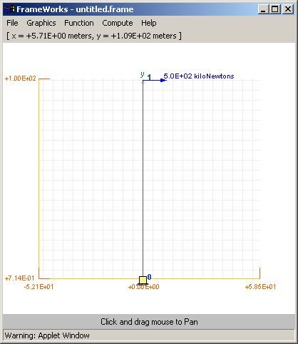
Figure 4.1 - Structure produced from StructureXML using Frameworks
Back
to Top
|
|
|
|
|